
The Two-Dollar Antenna Problem
I bumped into a design flaw in a cheap ESP32 board that could have crashed my project. With some good luck, and help from Claude AI, I found a good solution.
I'm building my grandson Sam a birthday present — a "black hole clock". Sam is into black holes at the moment, and the clock function should help him learn how to read analogue clocks. There will also be some games his phone can join over WiFi.
The brains are an ESP32-C3 "SuperMini" — tiny, cheap, and, as it turns out, notorious. By lucky coincidence, just as I was getting to the WiFi part of the project, I stumbled across a YouTube clip cautioning about the terrible WiFi performance of some of the C3 boards. Murphy's Law accurately predicted that the one I had bought was the worst offender: its onboard antenna and PCB layout are a terrible mismatch with the radio chip's 50 Ohm output, so instead of radiating properly, a good chunk of the WiFi signal bounces straight back into the chip as damaging heat, with a serious reduction in range.
I discussed the problem with Claude AI, and we found a well-documented fix: a short loop of wire, hand-soldered across the antenna's existing pads, corrects the mismatch without needing a new board.
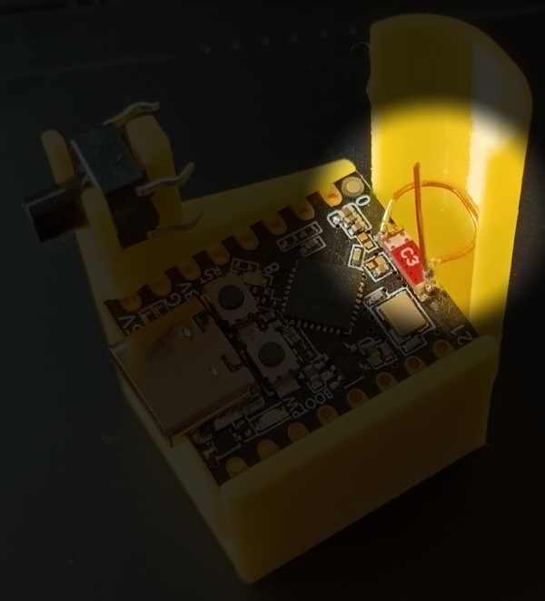
I am making a mount to hold the C3 board and a WiFi setup switch. The ceramic antenna and modification are spotlighted, with help from Claude.
The obvious question was whether it actually worked, especially as various online posts were in disagreement about the proper dimensions. Claude was instrumental in sorting through all that. So I had Claude write me a small test rig — the C3 as an Access Point (AP) broadcasting a webpage to let me adjust its transmit power from my phone. Meanwhile, my phone's Wi-Fi analyser app did the actual signal-strength reading. Then the fun part: the C3 fixed to a gatepost, my phone on a table 7.5 metres up the driveway (shaded in a cardboard box so I could actually read the screen), everything positioned to within a centimetre or two so the "before" and "after" runs were genuinely comparable.
The result: nearly 10dB better signal after the fix — roughly three times the usable range, right at the top end of what this fix is documented to achieve. Sam's clock will now, hopefully, have no problem connecting to his home WiFi so it can get the correct time from an NTP server. It only needs to update the time once a day, so I'll do that in the middle of the night, and at other times be in local mode so he can play games and learn analogue clocks.
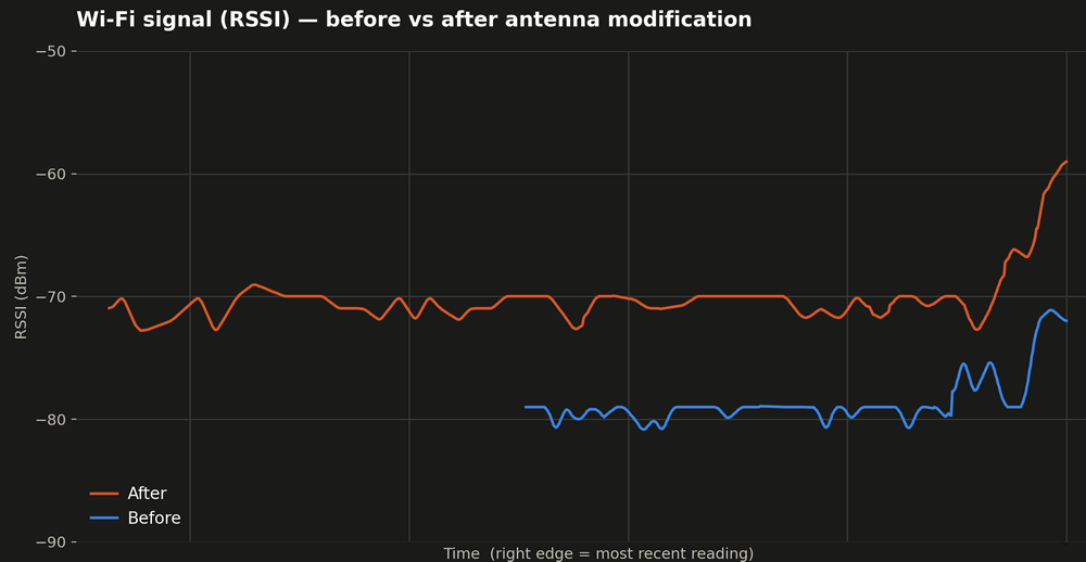
Composite before/after plot generated by Claude, while removing all the neighbours' signals and other "noise". The upticks at the end ar eme coming back to get the data - I went away for the test runs so my body movements wouldn't impact the readings.
Board info. The C3 board I did this with is this one:
https://www.aliexpress.com/item/1005007783677682.html If you take a look, you will notice that the red ceramic antenna is right up close to the small metal crystal oscillator. Therein lies the problem. The "rules" require a couple of millimetres of separation.
I have now ordered some of these:
https://www.aliexpress.com/item/1005009897797706.html They look to have a much better layout around the red chip antenna, and even come with an optional external antenna.
The antenna fix I applied is a 34 mm length of solid wire, with the first bit wound on a 5 mm mandrill, then opened up to fit the ceramic antenna, as shown above. The published information called for 1mm silver-plated copper wire. The closest I have is 0.5 mm solid copper from some salvaged telephone multi-pair cable (remember when telephones used physical wire?