
Introduction
These devices from Atmel (now part of Microchip) are the functional descendants of the original PAL, PLA, and GAL chips – though they are not necessarily electrically or pin compatible with the earlier devices. These are still highly regarded by the hobbyist community as they are all 5V devices; hence they can be used in many retro designs using the older 5V logic devices without needing level translators.
Note that there are 3V variants of these devices. Ensure you have the right part, or the magic smoke will escape.
While both the ATF16LV8C and the ATF22V10C are THT DIP packages, the ATF1502AS is an SMD PLCC-44 package. This can be managed for THT PCBs with a widely available THT PLCC-44 socket, and for breadboards with an adapter board, such as the ATF1502-EVB-PLCC Board or similar.
The instructions for the ATF1502AS should also apply to the ATF1504AS and ATF1508AS devices; however, I have not tested this.
| I/O Pins | Registers | Macro | Package | |
|---|---|---|---|---|
| ATF16LV8C | 18 | 8 | 8 | DIP-20 |
| ATF22V10C | 22 | 10 | 10 | DIP-24 |
| ATF1502AS | 36 | 32 | 32 | PLCC-44 |
ATF16LV8C
https://www.microchip.com/en-us/product/ATF16LV8C
ATF22V10C
https://www.microchip.com/en-us/product/atf22v10c
ATF1502AS
https://www.microchip.com/en-us/product/ATF1502AS
While I generally prefer to use Linux, and many of the tools described are open source/cross platform, several are closed source/propriority vendor supplied Windows only tools. Some people have had success with various workarounds to achieve Linux operation; however, this is not supported, and this article will only provide Windows instructions. At the time of writing, this is for Windows 11.
This article was only possible due to the many other articles and forum posts that provided partial solutions or clues to the complete solution. Some of these are listed in the References section at the end of the article; all have my gratitude.
Software
Use either Digital or Wincupl to create a JEDEC file to program the device.
Digital
Digital is an easy-to-use digital logic designer and circuit simulator designed for educational purposes.
Installation
There is no installation required; just unpack the Digital.zip file, which is available for download. On Linux, start the shell script, and on Windows and MacOS the JAR file can be started directly. A Java Runtime Environment (at least JRE 8) is required to run Digital. On Windows, the easiest way to get Java is to install the binaries provided by the Eclipse Temurin project.
If there are any problems starting Digital on your system, please try to run Digital from a command line within the Digital folder:
java -jar Digital.jar
Install by unpacking into C:\Apps\Digital\ and create shortcut on Desktop to digital.exe.
Usage
To create a design and generate either a CUPL file to be imported into Wincupl, or a JEDEC file to program the device (below).
Digital will use the current file (or last saved) directory for output. This can be a problem on start up as you can overwrite your last project output.
- Create the design using either the GUI or a Truth Table (
Analysis -> Synthesis). - From GUI design,
Analysis -> Analysis, then follow the steps for Table (below).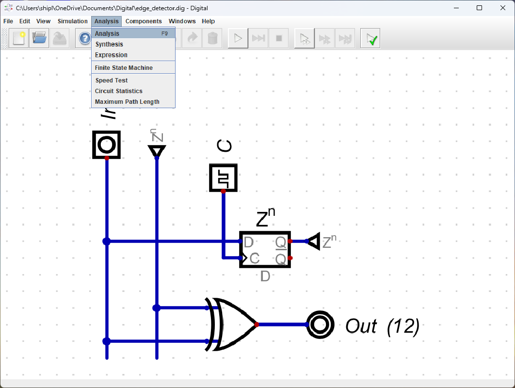
- From Table,
Create -> Device -> {GAL16V8, GAL22V10, ATF150X} -> {CUPL, JEDEC}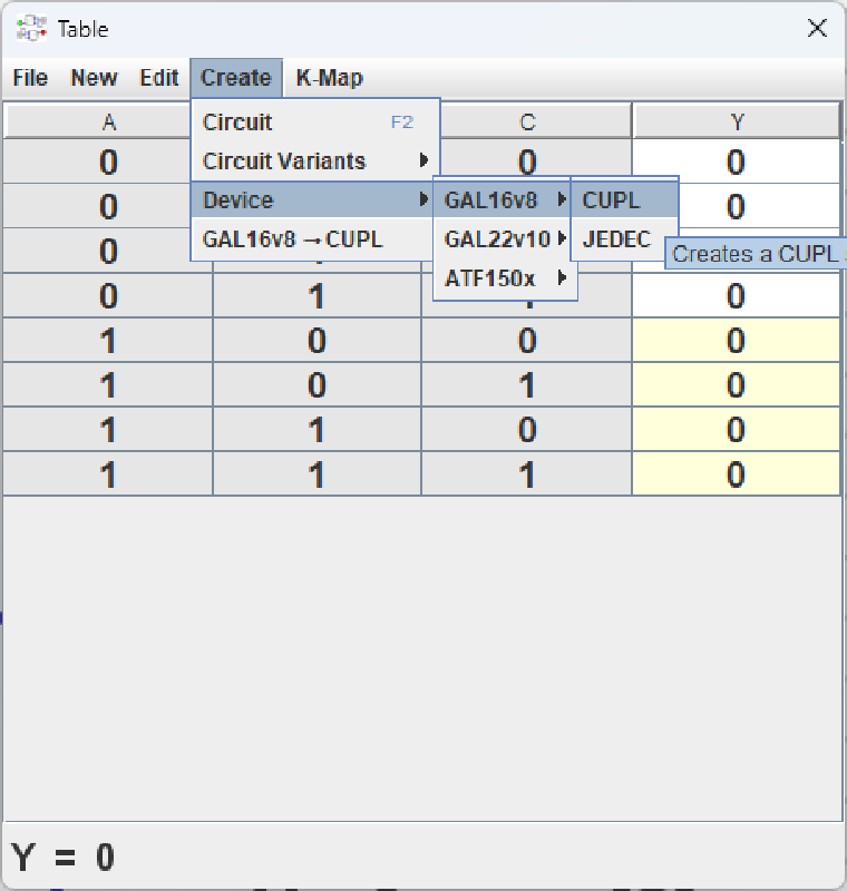
Wincupl
WinCUPL II, an intuitive and effective Windows based development suite for your PLD projects.
https://www.microchip.com/en-us/development-tool/WINCUPL
Installation
- Download the software .zip file and the appropriate device support files.
- Extract the files into the same temporary directory.
- Run the setup.exe file.
- CD to the WinCUPL installation path; I used C:\Apps\WinCUPL2\.
- Right‑click the folder → Properties.
- Go to Security → Edit.
- Select your Windows user (or the Users group).
- Enable Full Control, Modify, and Write permissions.
- Apply to all subfolders.
Usage
To create a JEDEC file to program an ATF16LV8C or ATF22V10C device using Xgpro and a T48 (or similar), or to program an ATF1502AS using OpenOCD and a JTAG programmer.
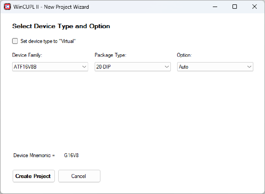


| Device | Package | Option |
|---|---|---|
| ATF16V8B | 20-DIP | Auto |
| ATF22V10C | 24-DIP | None |
| ATF1502AS | 44-PLCC | JTAG |
- Edit the .pld file using the
Design File Manager New/Editbutton to create the CUPL code, or import the file from Digital using copy/paste.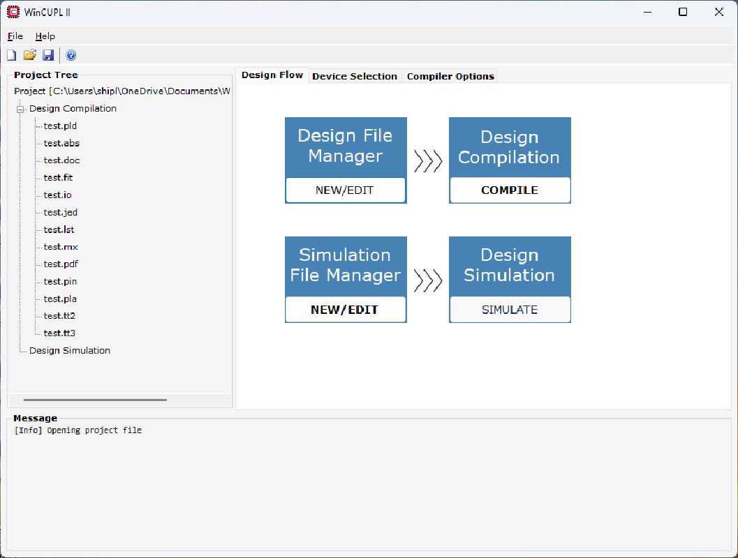
- Check the settings in the
Device SelectionandCompiler Optionstabs - Compile the design to create the JEDEC file (.jed) using the
Design Compilation Compilebutton - There should be a
Design compiled and fitted successfullypopup. - Check the
Messagelog for errors

Programmer
For ATF16LV8C & ATF22V10C
XGecu make a range of Universal Programmer devices, with the (now obsolete) TL866 being very popular. There have been several upgraded models, such as the T48 and T56. The T76 is the current model (at the time of writing). Any of these devices with the matching Xgpro software will work. I have the T48 model.
Warning: While the TL866 has been discontinued, there are still many for-sale listings online. These “clones” are not genuine and can damage the device being programmed. It is recommended to purchase programmers from the official XGecu store.
XGecu T48
Installation
The Xgpro software is Windows only. Just follow the instructions in the User Guide.
Usage
To program the device, connect the XGecu T48 and open the Xgpro application.
- Insert the device into the T48.
- Click the
Select ICbutton and find the device in the list. LOADthe JEDEC (.jed) file.- Ensure the
Erase before, andVerify afterare selected, and thatEncrypt chipis NOT selected. - Use
PROG.to program the device.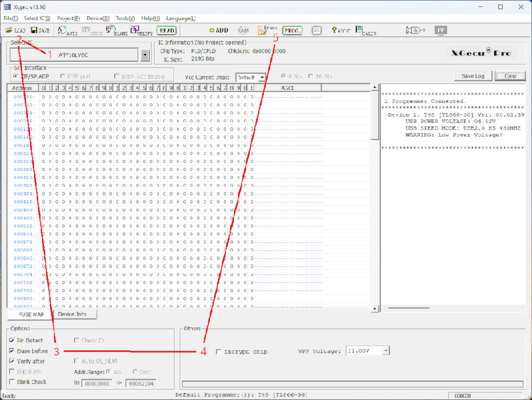
- Ensure that
LOCK Bitis NOT selected. !!IMPORTANT!! This requires special hardware to unlock. The T48 can NOT unlock this. - Click
Program.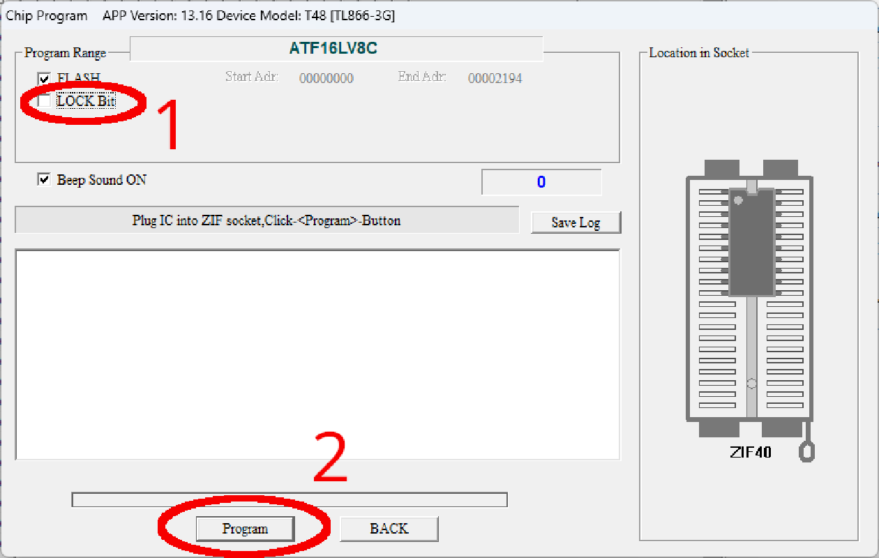


If the verification is successful, the device is ready to use.
For ATF1502AS
ATMISP7
This program could be used to program the device, but unfortunately, it only works with the proprietary ATDH1150USB cable. But it can still be used to convert the JEDEC file to the required SVG file for use with OpenOCD and a programmer adapter.
Installation
The ATMISP7 software is Windows only. Download the package and follow the instructions in the ATF15xx CPLD ISP Software – ATMISP Contents & Installation Instructions.
Usage
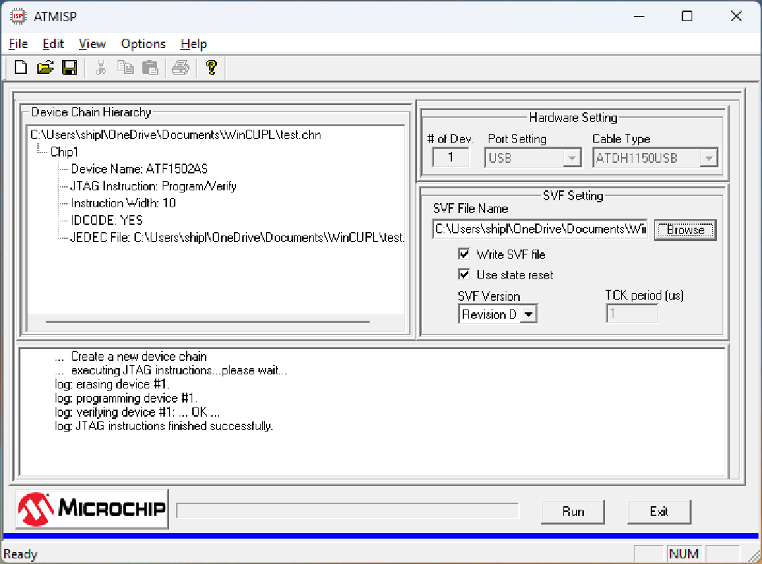
- Open the GUI
- Click File – New
- Click Ok for 1 device
- Select Device Name as
ATF1502AS - Select JTAG Instruction as
Program/Verify - Browse for and select the JEDEC (.jed) file
- Click OK
- Tick
Write SVF file - Browse for and select (or create) SVF (.svf) file
- Click
Run - Check log, expecting:
log JTAG instructions finished successfully - Check that the created SVF file is not 0 bytes in size

ATF150x-FT232-Programmer
This adapter allows OpenOCD to program an ATF150x device.
https://github.com/PaulShipley/atf150x-ft232h-programmer
An Adafruit FT232H Breakout board is required to provide USB to UART Serial communication.
All of the FT232 devices I have purchased from “unofficial” sources have been fake and/or non-functional – only obtain these devices from official suppliers. Mine came from Core Electronics.
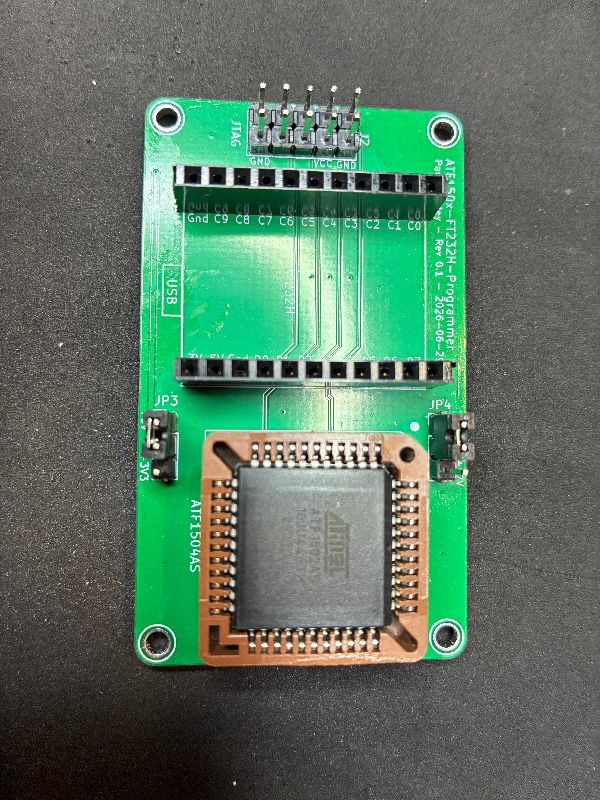
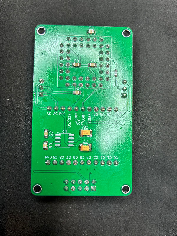
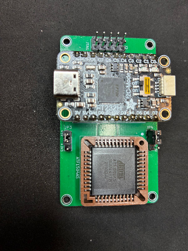
Important: Ensure that jumper JP3 is set to the correct voltage (5V or 3V), and jumper JP4 is set to Gnd (NOT 12V).
The programmer can also be built on a breadboard using the FT232H and a PLCC-44 adapter board.
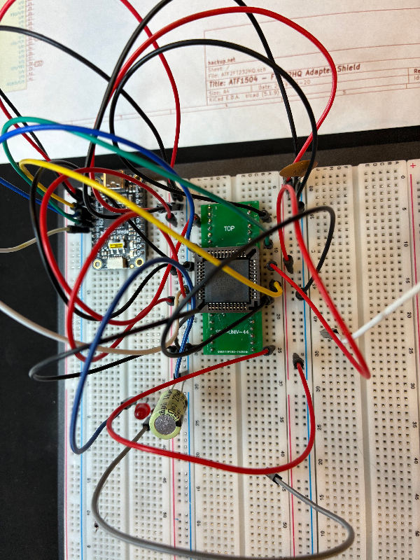
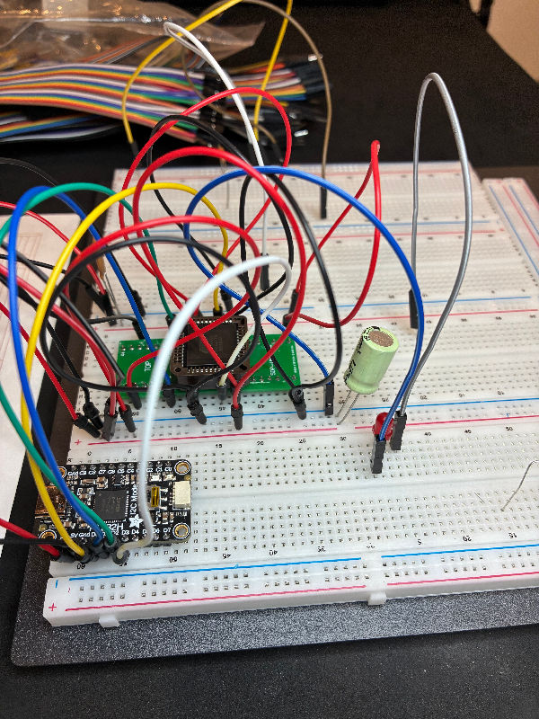
The official drivers for the FT232H can be found on the FTDI site.
OpenOCD requires the WinUSB interface, which can be installed by the Zadig utility.
- Download the
Zadigstandalone executable (no installation required). Keep this handy as you will need it again. - Connect the
FT232Hto the PC via USB. - Run
Zadig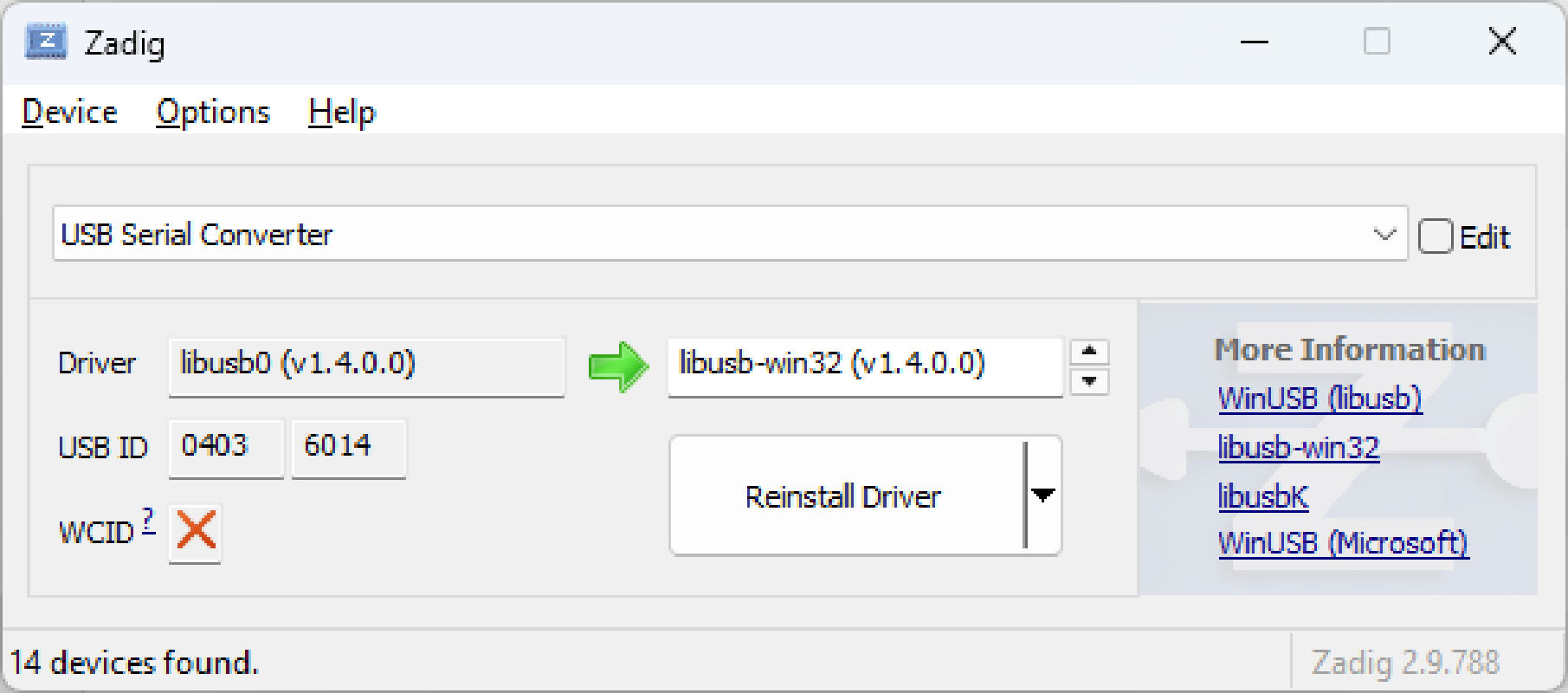
- Under
Options, clickList All Devices. - Click the device drop-down to see the full list of devices. There should be a device with a name like
USB Serial Converter; click that. - Confirm that the correct device has been selected by checking that the
USB IDis0403 6014. - Select the
libusb-win32driver and clickReplace Driver(if that is the current driver, the button will sayReinstall Driver). - Open
Device Manager. There should be both an entry forlibusb-win32 devices–USB Serial Converter, and an entry underPorts(COM & LPT)likeUSB Serial Device (COMn)– where n is any number other than 1, eg COM3.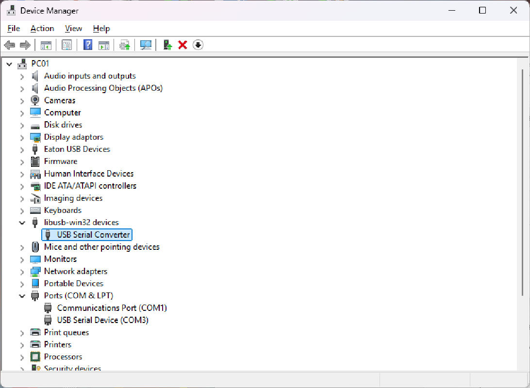
OpenOCD
The Open On-Chip Debugger (OpenOCD) aims to provide debugging, in-system programming and boundary-scan testing for embedded target devices.
Installation
- Download the archive https://github.com/xpack-dev-tools/openocd-xpack/releases
- Extract to C:\Apps\OpenOCD\
- Create the OpenOCD configuration file for the Adafruit FT232H, or similar, in C:\Apps\OpenOCD\openocd\scripts\interface\ftdi\ft232h.cfg
# SPDX-License-Identifier: GPL-2.0-or-later

#
# ADAFRUIT FTDI FT232H
# Any FT232H based board may work
#
# http://www.ftdichip.com/Products/ICs/FT232H.htm
#
#

adapter driver ftdi

ftdi vid_pid 0x0403 0x6014

ftdi layout_init 0x0030 0x003b

# Those signals are only required on some platforms or may be required to be
# enabled explicitly (e.g. nrf5x chips).
ftdi layout_signal nSRST -data 0x0010 -oe 0x0010
ftdi layout_signal nTRST -data 0x0020 -oe 0x0020

#transport select swd
adapter speed 400
transport select jtag


# Adafruit      FT232H    JTAG
# Name  Pin     Name      Func
#  D0   J1-3    ADBUS0    TCK
#  D1   J1-4    ADBUS1    TDO/DI
#  D2   J1-5    ADBUS2    TDI/DO
#  D3   J1-6    ADBUS3    TMS
#  D4   J1-7    ADBUS4    (GPIOL0)
#  D5   J1-8    ADBUS5    (GPIOL1)
#  D6   J1-9    ADBUS6    (GPIOL2)
#  D7   J1-10   ADBUS7    (GPIOL3)
#  C0   J2-1    ACBUS0    (GPIOH0)
#  C1   J2-2    ACBUS1    (GPIOH1)
#  C2   J2-3    ACBUS2    (GPIOH2)
#  C3   J2-4    ACBUS3    (GPIOH3)
#  C4   J2-5    ACBUS4    (GPIOH4)
#  C5   J2-6    ACBUS5    (GPIOH5)
#  C6   J2-7    ACBUS6    (GPIOH6)
#  C7   J2-8    ACBUS7    (GPIOH7)
#  C8   J2-9    ACBUS8
#  C9   J2-10   ACBUS9
Usage
Ensure that jumper JP3 is set to the correct voltage (5V or 3V), and jumper JP4 is set to Gnd (NOT 12V).
Connect the FT232H to the PC via USB.
Once the cable is connected and the board is powered on, use OpenOCD to program the device.
Use the Windows Command Prompt (cmd) to run OpenOCD.
Test the connection
C:\Apps\OpenOCD\bin\openocd.exe -f C:\Apps\OpenOCD\openocd\scripts\interface\ftdi\ft232h.cfg ^
 -c init ^
 -c scan_chain ^
 -c "sleep 200" ^
 -c shutdown
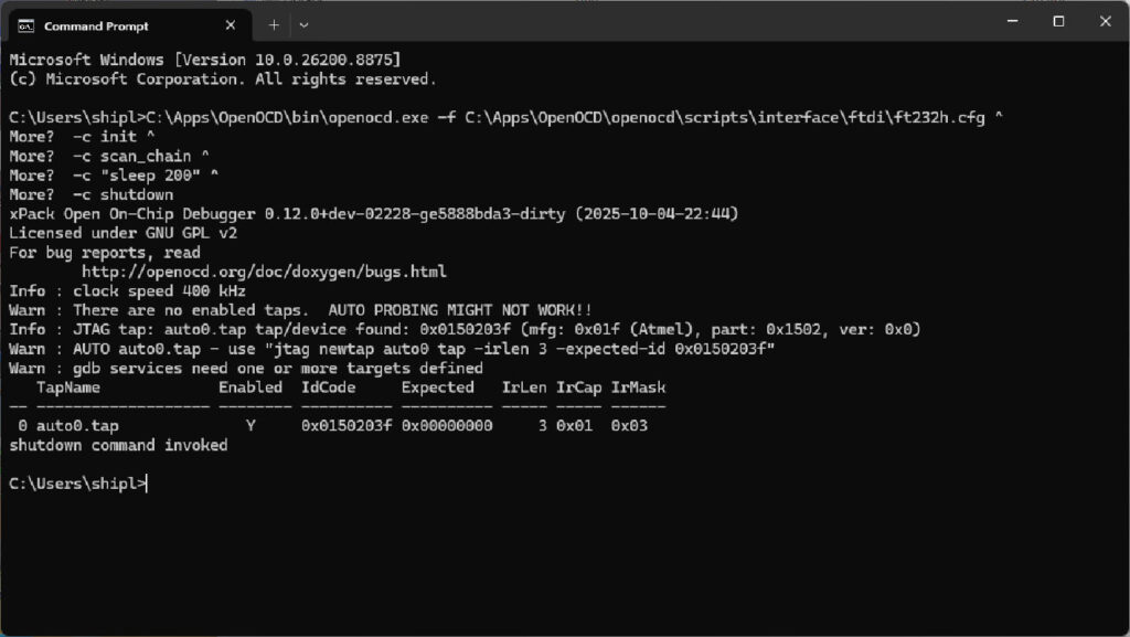
Program the device using test.svf file from ATMISP7 (or whatever file name you used)
C:\Apps\OpenOCD\bin\openocd.exe -f C:\Apps\OpenOCD\openocd\scripts\interface\ftdi\ft232h.cfg ^
 -c "jtag newtap ATF1502AS tap -irlen 3 -expected-id 0x0150203f" ^
 -c init ^
 -c "svf test.svf -progress" ^
 -c "sleep 200" ^
 -c shutdown
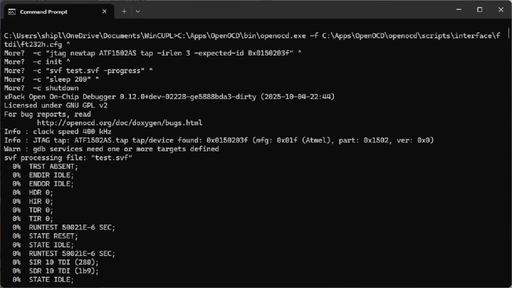
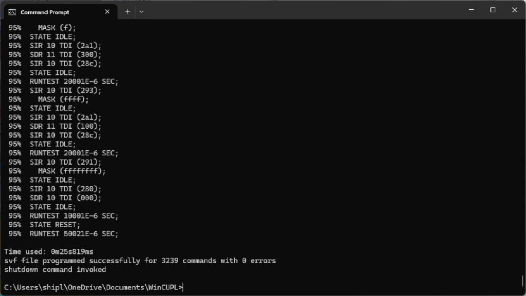
Check that successful commands are non-zero, and that there are 0 errors.
Erasing JTAG disabled devices
It is possible to program the ATF1502AS in such a way as to disable the JTAG interface, thus preventing any further modification. This can be removed and JTAG re-enabled by following the Erase procedure.
Note that I have not tried this as I do not have any “locked” devices; however, the process seems quite straightforward.
Using ATMISP7
- Open the GUI
- Click File – New
- Click Ok for 1 device
- Select Device Name as
ATF1502AS - Select JTAG Instruction as
Erase - Click OK
- Tick
Write SVF file - Browse for and select (or create) SVF (.svf) file
- Click
Run - Check log, expecting:
log JTAG instructions finished successfully - Check that the created SVF file is not 0 bytes in size
Using the ATF150x-FT232-Programmer
- Ensure that jumper JP3 is set to the correct voltage (5V or 3V), and jumper JP4 is set to Gnd (NOT 12V).
- Connect the FT232H to the PC via USB to power on the board.
- Change JP4 to the 12V position.
- Use OpenOCD to erase the device by programming it (above) with the “erase” file created by ATMISP7.
- Change JP4 to the Gnd position.
- Program the device normally, or remove power from the device (as required).
Important – failing to perform these steps in the correct sequence may result in damage to the device.
References
https://github.com/peterzieba/5Vpld/blob/main/PROGRAMMING.md
https://www.steckschwein.de/post/2025/07/cpld-upgrade-new-toolchain
https://www.hackup.net/2020/01/erasing-and-programming-the-atf1504-cpld/
https://github.com/marqs85/snes_dejitter
Reproduced with permission from Secret Diary of a Geek